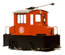
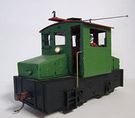
This is the Hartland "Sparky" out of the box.
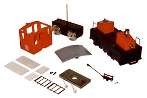
These are the parts of the diassembled Hartland "Sparky".
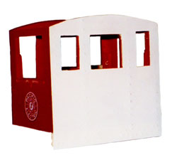
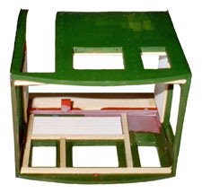
This is the cab with the new styrene sheeting added to increase the cab height.
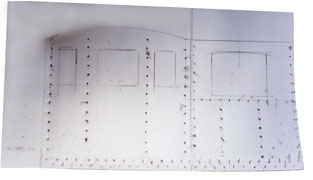
This shows the styrene sheeting after the cab has been outlined and the rivets have been punched in.
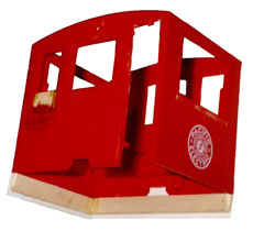
This lower view of the cab shows the wooden support pieces added to give strength to the new styrene siding. Note that the feft cab window has a block of wood in it to make the window depth equal to the neighboring window.


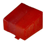
The above hoods show the progression of increasing their widths. Pictures one and two show the black plastic glued into them. These two are glued together to produce the hood in picture three.
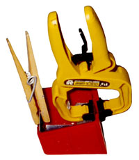
The hoods being clamped together to make the wider hood.
Parts for the next steps.
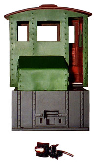
"Sparky" Cab on it's side, showing interior detail.
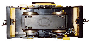
The underneath showing the installation of the Kadee Couplers.
This shows the slot that has been cut just above the original coupler placement.
Hartland “Sparky” Locomotive
Kit-Bash Project -- Part One
This is Part One, of a Two Part series to kit-bash a small electric locomotive. It involves the use of drills, paints, small metal, wood and plastic parts; knives and pliers. Best of all, you will bring your own imagination and creativity to the table.
Background
Hartland Locomotive Works produces (what appears to us to be) a nice, easy model to kit bash. In the reviews, (mainly Garden Railways) they state that the locomotive is of no particular prototype and measures out to 1: 24th (1/2") scale. Once ours was obtained and run around some, it is what could be called a “good runner.” So modifying the motor and gear train is one big item you’ll not need to worry about.
In measuring this model out, this might work out to be 1:24th scale, but there is lots of room for making this into a more realistic looking electric locomotive, again with no particular prototype in mind. In past experiences of looking at many pictures of single truck engines that have been either produced by a large manufacturer (GE, Westinghouse, etc.); home-built in the shops by the railroad itself or created from some other piece of equipment, there is not a lot of commonality to these creations.
Baldwin-Westinghouse produced a number of small 45–60-ton engines, even though they are double truck engines. They have clean lines, large hoods that cover the compressors and blowers. This is a single truck model. But the Baldwin-Westinghouse is the basis for this particular kit-bash.
Procedure
The first item that is noticeable on the Hartland car, is the roof, or ceiling height. On the model as produced, it is about 6 feet from floor to ceiling. Again, we are not saying that this height is incorrect, It is just that the model would “look” better with an “improved” higher ceiling. Maybe your railway or railroad has some clearance issues, and the model ceiling height could be an issue. Take some time to check these facts out to assure your new creation fits into your existing clearances. Nothing is worse than a nice model, venturing out on it’s first run, crossing paths with some obstacle that would ruin some or all of your work.
So, assuming you have your Hartland “Sparky” (as shown at left) or South Shore Line engine, lets start to work.
The engine: The first process is to take the engine apart. You should have a simple phillips screwdriver, a slotted screwdriver and a receptacle for the parts storage. Remove the trolley pole or pantograph. The Hartland model that is being used, was equipped with a trolley pole and required the phillips screwdriver to remove the screw attaching it to the car. Set the pole and screw into the storage receptacle.
Turn the engine over; there is a clamp affair that holds one end of the motor truck onto the body. The other end has a solid bar. Take the slotted screwdriver and pry the clamp with a twist motion (between the engine block and clamp) to ease the engine (motor) block out beyond the end of the tab. Once this end is free, the other “solid” end should come loose automatically. The motor block should come out and the “light pole” with it. Twisting the clamp might take you a moment to get it worked over the tab. Set the motor block aside.
There are two Phillips screws under the floor area, remove these and the cab should come of the base or frame. Set the cab aside and also the two weights. Remove the hoods from each end (lift up by the cab end and they should come off easily). Turn the frame over; remove the handrails and the 1/2 round air tanks on each end by squeezing the tabs. Set these parts aside. The frame should be clear of all items.
The cab: Remove the windows, headlight lenses, roof. Set the headlight lens and the windows aside.
At this point, at left, the car shell, frame roof should be stripped of all the parts and stored.
Now the challenge is about to begin!
1. Some materials you need to have to complete this project are; Styrene sheets (Evergreen sheet styrene, .010 thickness), various small wood strips, small size plastic and brass angle pieces, thin flat plastic strips, glue, etc.
2. One decision already made was to add to the ceiling/roof height by 1 scale foot, and to add rivet detail to this model. Some considerations you might want to think about; headlights? Do you keep the ones on the model, or add new ones? Same with window glazing, etc… We chose to add rivets, add new headlights, and will add window details.
3. Beginning with the cab, being very careful: cut off the headlight barrels from the cab ends and sand the areas smooth. Cut off the small detail piece under the side cab windows to make this smooth. You want the sides of the cab to be fairly smooth so when you glue on the styrene sheets, they attach with out too many big bumps that will show later on. If you want the engine to look like it just arrived from the factory, a “show room” piece, you’ll want to sand these areas very smooth.
By not sanding so smooth, there will be more texture. It will look more like a version of a working engine. Simulating an engine during it’s life on your “railway” which would have taken some beating over the years and would not be quite so perfect.
4. At this point, it was decided to make the front, lower window heights all the same. Measure the size of the area, cut some small wood pieces, fill in the lower portions of the front drivers window and the door window and glue into place. You can see how this will eventually look in the photo at left.
5. To add to the floor height, take one of the styrene sheets. This will be used to create a new side skin or side sheets for the entire cab. Taking your styrene sheet, measure 1/2" (= 1 scale foot) from the lower edge. Draw a new line paralleling that lower edge 1/2" in height. Now take the cab, and out line each side and each end on the styrene. Use a sharp pencil while doing this. Also, be sure to outline the windows. This will take more than one sheet of styrene for this model.
6. If you want to add rivet detail, this is also now the time. Draw straight parallel lines about a scale 3 and 6 scale inches up from the lower edge of the styrene. A few equally spaced lines vertically, about 3 scale inches from the side edge one down the middle, and one across under the window.
7. Using your ruler, mark off spacing, about every 6-scale inches where the rivet will be. Again be careful when doing this, as this is what people (including you) will later see.
8. There are many ways to create rivet details. In this case a small center punch and a very small brass hammer were used. Underneath the styrene, lay a small piece of soft plywood. Placing
the center punch on the line and space marked off, and a very slight blow of the hammer, you are knocking in the rivet detail.
Note: You may want to practice a bit of scrap styrene materials to perfect your technique!
9. After knocking in all the rivet detail, check the “exterior” and see how it looks, did you miss any, some more needed in some areas. Did you rivet across the lower doors areas where you should not have?
10. Very carefully, using a metal straightedge and knife cut the four walls apart. Leave some extra material at the top edge. This will be trimmed later after gluing. Carefully fit the sheets to each cab wall, do they line up OK? Windows, not yet cut out, look OK? Rivet details is in the right places? Cut some small wooden strips, which will act as the lower parts of the cab wall (to fill in) where there is now no material other than the styrene. When measuring the amount of wooden spacer or filler needed, leave a little edge of styrene lower then the wooden piece. This can be trimmed later as needed.
11. Another decision was that one door should be “opened.” Very carefully cut one door out using a saw and exato knifes. Make this an open doorway as shown in the photo at left. Set the door aside, use some styrene and wood to increase the door height. Set aside as this detail will be glued on later.
12. If things look good, and line up well, smear glue onto one cab side, and lay on the styrene materials, clamp or add weights to insure a good strong bond between the cab and the styrene. Let this sit overnight at least (or say 10-12 hours). You’ll want the styrene to be well bonded to the body before moving it. Glue all four sides, and glue the lower wooden fill part. Make sure this wooden piece is parallel with the car sides.
13. After the glue is dry, carefully start to cut out the window areas. If you want, start to prime and paint the styrene as you go along.
14. For the “hoods” these needed to be widened. Carefully cut length wise, basically in halves. Measure how wide they need to be on your model. Add some heavy plastic pieces to the inside that will reach across to the other half of the hood. Glue the plastic to one side only first, and clamp. After gluing these together, let them sit and let the glue harden well.
After they were carefully glued together, some wooden filler pieces were added for strength and then some styrene (with rivet detail) was carefully added over the top and front side. Again leaving some extra materials to be trimmed off later.
15. The roof needs to be filled in with wood and modeling filler to make the roof skin smooth, and added some to the inside ceiling to make this smoother. Measure and cut small pieces of wood for trolley cleats and also cut some trolley boards to length. These were made to extend over the cab roof ends about 3/4" (18"scale inches). You can also start to paint the roof. We chose a reddish color, along with the boards.
16. For the main frame, cut off the rounded extension between the two-journal boxes at the lower edge of the frame to make this part straight (on each side).
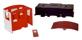
17. The next photo shows the cab, cab door, main frame, roof. You can see the cleats have been sanded to fit the roof contour and glued in place.
One suggestion is to try to put the pieces of the model together from time to time, see how it all fits together (or doesn’t, in some cases)!. You’ll be able to cope with the smaller fixes and repairs now, rather than later when everything is painted. You will have a better chance of a successful kit bash. Remember, we all have to start somewhere, and skills take some time to develop. Ask your local hobby shop, or email LRP with your thoughts.
In Part Two, we will finish the cab, roof, and frame. We will add the trolley pole and base, trolley pole hooks, Kadee couplers, interior details, and paint and finish the model.
Kit-Bash Project -- Part Two
Details Products used:
LRP #005 Trolley Hooks (Modified)
Paint-Frame -- Engine Black by Floquil
Cab exterior -- Reading Green by Polly Scale
Roof -- Rock Island Maroon by Polly Scale
Kadee Couplers 821 or 921 (921 is painted red)
Trackside Details TD-46 Brake valve
Continuing with the Kitbash of “Sparky” the electric locomotive: Cab, hoods, frame…
Cab and Hood details
18. The interior of the cab was outfitted with some small wooden strips to outline the “framing” of the cab walls, window frame area and door jams. V grooved siding (left over from another job) was placed horizontally in the cab, below the front windows. The cab was painted in the same red color as the roof, although the cab of our model has seen some service, the paint did not cover 100% of everything, leaving some streaks here and there. Be sure to test fit the roof occasionally for proper fit.
19. The work continued with the hoods. Making these two hoods, when all glued together, be as true to each side as possible took some patience. One end took several tries to make it look right. Even then, when one of the hoods was placed on the car frame (deck) it still was not flush with the deck. One glue joint was again broken, and reset. Only this time, after applying the glue, the hood was set in onto the frame, and held in place with a rubber band so it would be straight in the end. And it worked.
20. Two small modifications were made to the frame: One was to cut off the eighth rounded (flywheel?) from the frame between the two journal boxes. The second was to fill in the small indentations where the original “Sparky” handrails were attached. Make this flush. A small piece of thin wood was used to fill in, and then modeling putty to fill the small gaps. Sand and paint.
21. This would also be the time to decide where the headlights should be placed. These were placed in the center, just under the window. (The headlight placement came later, which caused some other grief.) Bore or drill out the holes for the headlight.
The other consideration on where the is placed, is clearance for easy removal of one of the hoods for servicing the batteries. Since the hoods were originally held in with some clips on the front of the hoods (which were kept) the one hood that will hold the batteries will need to be easily removable for servicing the batteries.
Having the headlamp in the area now causes some clearance difficulties with the hood for servicing the batteries. The latch tab, that would help to hold the hood firmly in place, was cut down. If you cut this down (not totally off) your hood will be some what held in place by gravity, and so care will need to be taken when lifting and servicing this locomotive after this!
22. Since these headlights (LRP #007) will be battery powered, the batteries will be under one of the hoods. In usual practice, triple A (AAA) batteries are used. However, the hoods are just a little too short for these to fit. So two “N” (1.5 volt) batteries are resorted to for powering the headlights. There is clearance for two of these under one of the hoods. The on/off switch location has not yet been determined at this writing). The battery holders were glued into the deck.
23. This is a good time to add the couplers to each end. Kadee #821 were used. Recently, Kadee came out with a new product #921, which is an #821 painted red. The original “Sparky” coupler has been removed prior. New slots need to be cut approx. 3/8’ up into the frame, and wide enough to accept the coupler box frame. Heights were also checked using a Kadee coupler gauge. A 1/2" X 1/2" redwood (or any wood will do) was used to back up the Kadee coupler and act as the mount.
Measure across the width of the opening of the frame, and cut two pieces to length. Once you have assured yourself that your new hole for the coupler is at the proper height, glue this block of wood onto the end of the frame. Once dried, insert the coupler + box frame (all pre-assembled), and drill a small hole into the wooden block and insert a small #2 screw into this (see photo: This is of an earlier Hartland Mack engine, which has the same basic frame and cab as “Sparky”). A small piece of styrene should be cut and glued over the holes left that held the original “Sparky” coupler.
24. The cab should now be secured to the frame. Recall that 1/2 inch was added to the cab height. A #6 X 3/4" brass wood screws were used. The one end hood that will not hold the batteries can now be secured to the frame. Glue was used. Some small angle (brass) was also used to hide the outer edges of the floor and sidewalls, as there was a small gap. Glue in place and touch up with some red paint. Also, this is good time to paint all of the frame deck, sides and floor with black paint.
23. The brake stand was also glued in at this point. Since this model will only have one control area, only one brake stand is needed. The headlights were assembled and glued into place. Test and be sure your hood can still be taken off relatively easily.
26. The door that was removed earlier, was painted red on the inside and green on the outside. Also a hole was drilled for a door
knob to be added. A small round headed brad was glued in place that resembles a doorknob. Glue this door into place.
27. Two LRP # 006 Trolley Catchers were glued onto each end.
28. Paint the model cab and hoods. A dark green paint was used for this model.
29. Clear styrene was added into the front and door window areas.
Roof
30. So far the roof cleats; boards and roof have been painted. One LRP 004, Trolley Base + Pole were assembled. The base was painted red (like the roof) and the pole black. Do not paint the wheel where it will contact the overhead wire. The trolley boards were drilled to accept the trolley base mounting plate. Also, smaller trolley boards were used (as for the width) and now of course the trolley hook legs stuck out too far for this. We wanted the hooks to be high, so when next to a boxcar or other tall equipment, the pole will not interfere should it be in the hooked position. The legs of the hook were bent inwards (toward each other) slightly and then holes for the mounting pins were drilled, and the hooks then glued onto the boards. This was all assembled and glued onto the cab roof, and the pole inserted into the base hole. This should swivel freely.
Next installment: completion
New handrails, battery switch, interior details (cab seat, controller, bench, …) Grab irons up to roof. Final paint. Rope for pole. Look for these in the next installment.
© Light Rail Products